Tuesday, August 31, 2010

More Skins

Wow!  This takes a lot of time and some of it is very tedious work.  I spent one whole day building this Center Vent.  I wanted a certain finish so I wet sanded with 220 then 400 to get the desired finish.  I took a lot of work and several sheets of sandpaper but I am happy with the results.  I then glued the parts together with JB Quick.

This is the 3/4 rear door after gluing and some cleanup.  Spent most of a day picking JB Weld out of the seams with picks and old xacto knife blades.

Test fitting the front skins after gluing.  Everything looks good so far - now to get these cleaned up.  All of the remaining panels will be hinged.

Friday, August 27, 2010

Skin

So I dug out my skins that I have been saving since 2004!!  They look great and will be fun to get these fitted.  A quick test slide on to the frame shows all is well.

First I used a hacksaw blade to gently remove all the panels (after marking first) then I filed all the openings smooth. A jig saw was used to carefully cut out my 3/4 rear door.

Here is the back panel after gluing the two parts together with good old JB Weld.  I cleaned the excess off with a popsicle stick with a squared off edge.  I only have enough clamps to do a few parts at a time so I will do the front skins tomorrow.

Tuesday, August 24, 2010

Legs

Started to work on the legs, all the tedious little things that need to be done.  First I had to notch the bottom edge of the leg so they would clear the bolt heads that hold on the ankle trim.  Then (shown above) I started drilling notched holes to attach the booster covers.

I used files to clean up the holes, man do I want a milling machine!!

Legs at this point.  I still need to drill more holes for the shoulders and shims but am waiting for those parts so I will do that at a later time.

Foot Hoses

Today I made the outer foot hoses.  The hose is the braided polished brass sink hose from Lowe's.  I cut these open with a snip then pushed out the braided rubber hose inside.  Next I replaced the internal hose with some 7/16" clear tubing also from Lowe's.  This made the outside measurement exactly 1/2" so the hose would fit into the hose fittings.  I super glued each hose end so it would not come unbraided and sanded smooth.  These are a very tight press fit into the hose fittings.

Monday, August 23, 2010

Foot Work

Finished up the feet today!  I removed the drive frames and tightened and locktited everything, adjusted the chains and re-installed.  I also spent some time getting the motor mount/motor in just the right place so I could fit the battery box over the motor.  I also installed the wire section through the ankle and bolted in the hose fittings and aluminum strips in place.

Fitting the battery box was tight.  I had to sand the tops of the motor a bit on each side to finally get it to clear.  I also need to space out the box just a bit from the foot as the fit around the bottom just wouldn't match up with it flush.  I used two studs that dropped into slots in the feet to hold the top edge on and two small bolts in the bottom to tighten in place.  Everything finally fit and looked great.  I also added the cylinders and other fittings while I was at it.  I am still missing a few parts (the battery box straps) but should have those soon.  I will also add the cables in a few days.

Bottom view shows the motor fit up in the box, the tight fit of the chains and overall layout.  I am pleased with how everything turned out.

Painting

Spent some time painting some of the detail parts for the feet as well as the dome base ring.  I am using the "Krider" method with Cobalt Metallic Blue Rustoleum, followed by Duplicolor Blue Anodize and then Dupilcolor Clear.  Leaves a nice deep finish.

This is a side shot of the foot cylinders with the camera flash.  Note the different appearance to the same part below without the flash.  The paint has a color changing quality in different lighting which looks great.

Cylinders ready to install.

Sunday, August 22, 2010

Test Drive

So with the drive system mounted in the feet a test is in order.  Here is the first picture of R2 "standing" on his own.  Everything mounted up just fine.

After this shot I wired up some speed controls I had in the shop and drove him around for a bit.  Everything worked fine!!  My front foot casters moved just fine and driving was a snap.  I also took R2 out to the Galaxy Hobby Sci-Fi model club meeting and showed him off with progress so far - was a great day.

Friday, August 13, 2010

Drive Feet

One hitch when I put my drive frame in the feet is that the idler gear hit the shell.  I had to cut down the gear and shorten the shaft.  The standard gear is on the left and the cut down gear on the right.  Me and my hacksaw are becoming best friends.

Another hitch is that with the wheels in I was having a heck of a time reaching the nut that holds the frame to the foot.  I took one of my 7/16" end wrenches and bent a curve into it which made it easy.

Yes!!  Finally three feet with drive systems ready to install.  I could have it running in a few days.

Thursday, August 12, 2010

Center Foot

Got my parts back from the powdercoater, they are super nice.  I am especially happy with the steel parts beccause now rust is a thing of the past (I hope).

Center foot bottom view showing the mouting plate installed.  You can see the 4 studs sticking up that will hold the caster bracket and the locknuts on them so I can adjust the height.

Finished foot with casters all installed and ready to roll.

Center Ankle

My R2 is going to be quite heavy and I have and early version aluminum ankle which I have heard may bend in this type of use.  I thought about ways to reinforce it and finally decided to use some 1/4" aircraft plywood.  I made a center core of 3 layers and a crosspiece of 1 layer that notches over this.

Here is the finished part showing how it will fit into the ankle.  It is a nice tight fit and fills the entire bottom of the ankle.

This shows the installed part (before gluing).  It rests snugly against both sides and will also rest against the ankle mount on the body.  After this picture I coated it with JB Weld and fitted it tightly in the ankle - the JB weld will fill any gaps left around the bottom bushing.  This should do the trick and the ankle feels very solid.

Tuesday, August 10, 2010

Drive System

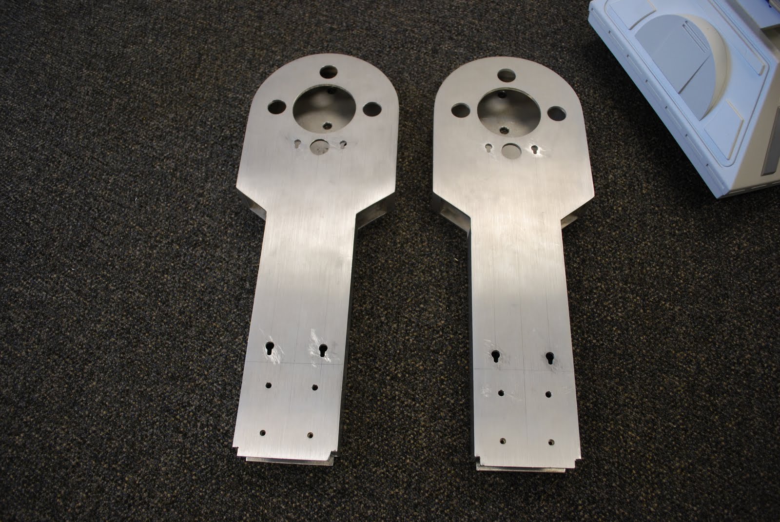
I took my foot shells and a few other parts off to the powdercoater so I thought it would be fun to work on the drive system while I wait.  This shows the parts I needed to build one foot's drive system.  I am using the Senna frame design but modified it slightly.  The side frames have larger (1 1/8") bearing holes as I am using ball bearings instead of bushings.  I also made the motor mount brackets 2 3/4" wide instead of 3" so they are reversible and fit easier in the foot.  The #35 gears and chain came from surpluscenter.com

This top view shows the 1/2" keyed shaft going through the frame/bearings.  The spacers are AN 960-816 aircraft washers.  Shown on the left is 1 AN 960-816L washer (which is the thin version) to keep the gear from hitting the bearing housing.  On the right I used 3 AN960-816 washers to keep the chain from hitting the bearing housing.

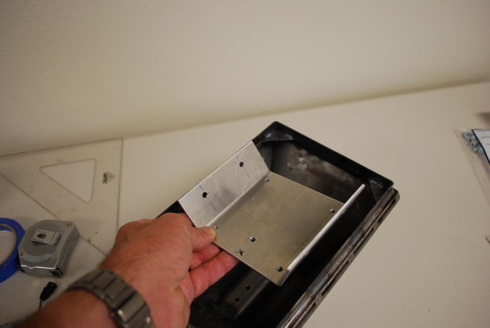
Here is the motor mount bracket mounted with 2 bolts just to get everything fitted up.  I used AN4-6A bolts with a AN960-416L (thin) washer on the outside and a AN960-416 washer and AN365-428 locknut on the inside.  This way everything fits fine and no bolts need to be cut.  The aircraft hardware is far superior to anything else you can use, comes in many more sizes and is dirt cheap compared to the hardware store stuff.  I buy it online from Aircraft Spruce & Specialty.

This shows the gears and shafts all mounted up.  I used a flanged bronze bushing in the center idler gear.  I looked into ball bearings but I felt the small size would not hold up to the loads, plus getting them to stay in the gear was a problem.  I used 2 AN960-816 and 1 AN960-816L washer under this gear for a spacer.  The idler shaft is a 1" piece cut off the motor shaft.
Top view of the frame showing all the gears, collars and spacer washers.

#35 chain fitted to the gears.  I never fitted chain before and finally found a chain breaker at Harbor Freight that worked well.  Also I wound up using 4 of the offset chain links instead of the standard type to get the chain the correct length.

Finished drive systems.  I ran them for a bit with a 12v battery and they work just great - I am really pleased.  Super thanks to Mike Senna for a great design.  I can hardly wait to get my feet back to try this out.

This is a bottom view of the finished frame.  To mount it to my metal foot I will use AN4-6A bolts with an AN960-416L under the bold head (ouside the foot) and a large AN970-4 washer inside the foot shell.  The AN970-4 washer really distributes the load and should keep the frame very solid.  This bolt setup has a tensile strengh of 125,000 psi so two on each frame will be plenty!!  When I wrote this the bolts cost only 14 cents each.  Also the fine thread bolts just never loosen up under use - important in the drive system.

Friday, August 6, 2010

Outer Feet

My outer feet were also early versions so I had a metal shop cut out the sides so I can mount a motor drive system.  That steel is HARD and I just don't have the tools at home required to cut it.

This is the bottom of the foot showing the drive frame bolted it.  I will show a buiild up of the drive frames later.

This shows what the bolt heads that secure the drive frames look like from the outside.  Once I get it all painted it should not show up too much.

Outer shot of the foot with the details in place.  The reason I wanted to work on the feet now is that I am planning to get the foot parts powdercoated.  I think this will be a better, stronger finish than paint and my guess is that the feet will take a lot of abuse.  Also the steel rusts so the powdercoating should be better protection from that.  The feet are ready now so off I go to the powdercoating shop to see what thay can do.

Thursday, August 5, 2010

Center Foot

My JAG center foot was an early version with a rather large bottom lip.  I took it to a local metal shop and had them open up the bottom to make more room for the casters and then they welded a 1/2" lip on to make the foot slightly taller and help hide the casters.
While at the shop they found me a 4" x 7" piece of 1/8" thick aluminum and bent it to match the inside dimensions of the foot.  I then drilled holes in it to match the existing holes in the foot.
A trip to Lowe's produced some really nice 3" casters.  Here I am drawing up the dimensions of the bracket that will hold them.  This picture shows that casters pointing towards each other.  I don't want it to be possible to hit each other in any direction.  With about 3/16" between the casters when pointing together the overall length when pointing apart is about 9".  The area in my foot is about 9 1/2" so everything fits fine.
The same Lowe's had some nice 1 1/4" aluminum angle that I used to cut the brackets to hold the casters.  A simple hacksaw and bench sander made up the parts fine.  The casters have a very strong base and when bolted up to the aluminum angle produce a very strong but light part.  I used 10-24 size hardware to attach the casters even though they have a very large mounting hole in them.  This actually made it easier to fit everything together and when tightened up didn't matter at all, turned out very solid.
This is an end view showing the bolts that hold the bent aluminum plate to the aluminum angles.  I used 2 1/2" long stainless bolts and stainless locknuts and washers.  The bolts are put into the bent plate and bolted down.  Another nut was threaded on then a washer, the aluminum angle and another washer and nut.  This way the casters can easily be adjusted up or down (about 3/8" each way) to adjust the look and ride of R2.  On the long stainless bolts I use a bit of anti-sieze on the threads to prevent galling - very important as I ruined one of the bolts when I forgot.

Finished unit resting in the foot.  I adjusted the height so the wheels have 1" of clearance to the bottom of the foot lip.  Total adustment range is about 3/8" either way from that.  I sat on the foot to make sure it's strong enough (it is) and the casters work really well.  The caster unit (without the foot shell) weights about 2 1/3 lbs.