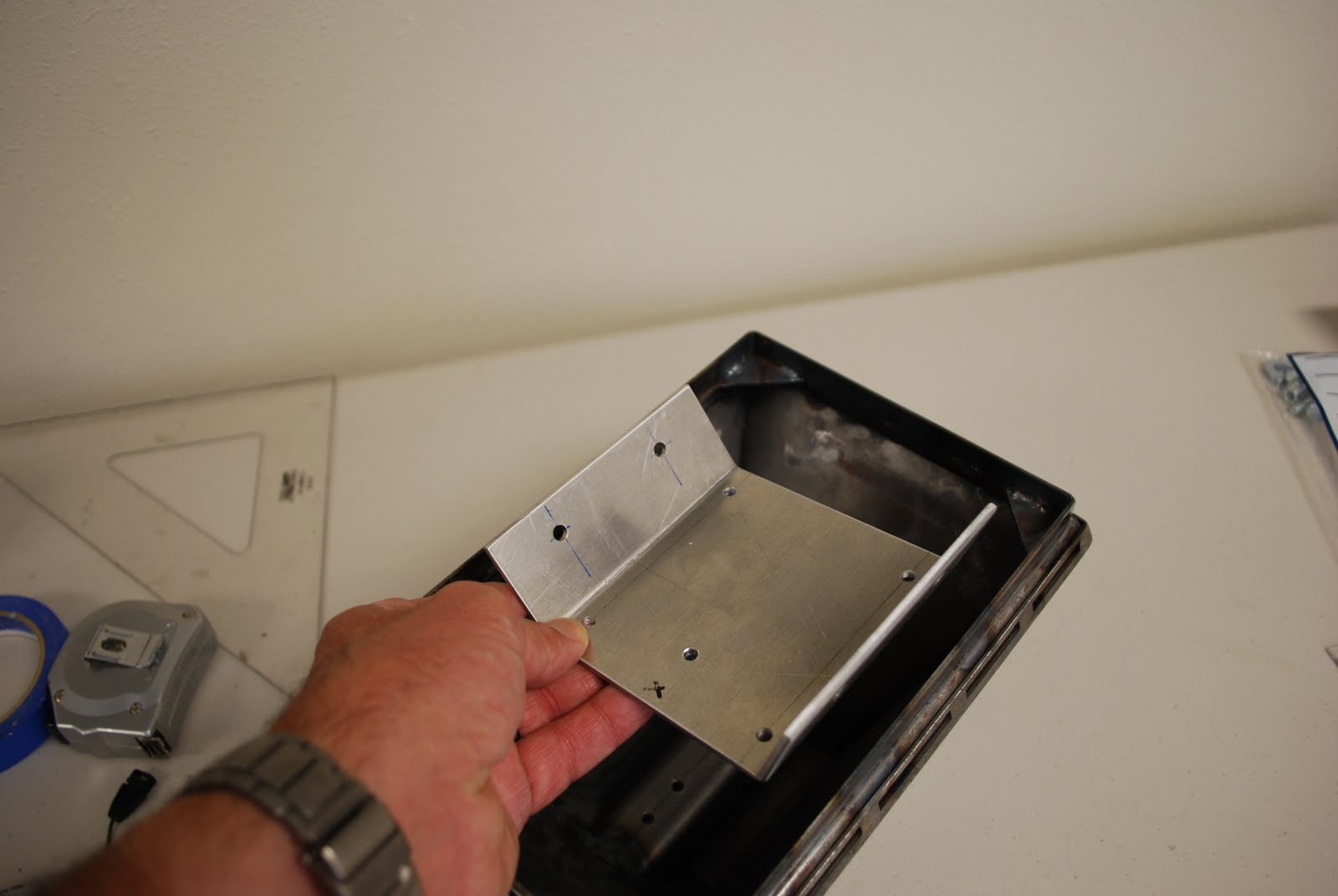
My JAG center foot was an early version with a rather large bottom lip. I took it to a local metal shop and had them open up the bottom to make more room for the casters and then they welded a 1/2" lip on to make the foot slightly taller and help hide the casters.
While at the shop they found me a 4" x 7" piece of 1/8" thick aluminum and bent it to match the inside dimensions of the foot. I then drilled holes in it to match the existing holes in the foot.
A trip to Lowe's produced some really nice 3" casters. Here I am drawing up the dimensions of the bracket that will hold them. This picture shows that casters pointing towards each other. I don't want it to be possible to hit each other in any direction. With about 3/16" between the casters when pointing together the overall length when pointing apart is about 9". The area in my foot is about 9 1/2" so everything fits fine.
The same Lowe's had some nice 1 1/4" aluminum angle that I used to cut the brackets to hold the casters. A simple hacksaw and bench sander made up the parts fine. The casters have a very strong base and when bolted up to the aluminum angle produce a very strong but light part. I used 10-24 size hardware to attach the casters even though they have a very large mounting hole in them. This actually made it easier to fit everything together and when tightened up didn't matter at all, turned out very solid.

This is an end view showing the bolts that hold the bent aluminum plate to the aluminum angles. I used 2 1/2" long stainless bolts and stainless locknuts and washers. The bolts are put into the bent plate and bolted down. Another nut was threaded on then a washer, the aluminum angle and another washer and nut. This way the casters can easily be adjusted up or down (about 3/8" each way) to adjust the look and ride of R2. On the long stainless bolts I use a bit of anti-sieze on the threads to prevent galling - very important as I ruined one of the bolts when I forgot.
Finished unit resting in the foot. I adjusted the height so the wheels have 1" of clearance to the bottom of the foot lip. Total adustment range is about 3/8" either way from that. I sat on the foot to make sure it's strong enough (it is) and the casters work really well. The caster unit (without the foot shell) weights about 2 1/3 lbs.