Sunday, October 31, 2010

Current Status

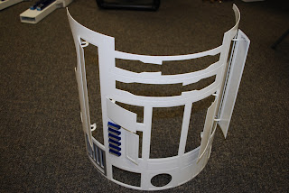
Today I got the legs finished up and re-installed so I decided to put together what I have so far to see how everything looks.  Gosh!  this is really fun :-)  R2 actually is starting to look like something and all the parts fit.

Rear view showing the electronics panel.  The top of the panel hits the skin (just barely) so it will need some trimming, other than this all is well.

Side view showing complete legs.  Only thing the legs are missing are the lower ankle cylinder holders.


Saturday, October 30, 2010

Dome Electronics

Today was spent making an electrical panel for the dome.  I used a piece of 1/4" ABS.  I really am starting to like the ABS, it looks good, cuts easily on my bandsaw, drills perfectly, and won't short out components that accidentally touch it.  I thought for a long time about how to clip in the wires coming from the slipring so they wouldn't hang up on something but finally realized that a simple slot would do the trick.  I slotted the panel and then faced the board and DB plug the opposite way so when the connector is plugged in the wire will not come out of the slot.  This is very simple and easy to hook up from underneath, very important as I plan on removing the dome for transport.

This is a view of the slipring and slot taken through the rear door.  Easy to see the slot in this view.

Close up of the board, cable hood and wire.  The slot is harder to see in this view but you can get the idea.  Later I'll drill some holes in the ABS to run small black tiewraps through to secure the wiring.


Friday, October 29, 2010

Electrical Panels

Time to build some electrical panels so I went to Tap Plastics and found some nice ABS black plastic that has a wrinkle finish on one side.  The main panel (above) and head panel are 1/4" thick and I will have two small side panels inside that are 1/8" thick.  The hinges are cut from a strip of aluminum aircraft hinge, very strong and light.  The hinge pins will be easily removable so I can take the panel off easily for service.

Shown above are the hinges for the panel installed.  The pins just slide into the hinge and snap in the nylon bracket to lock them in place.  Works slick and the panel comes off in just a few seconds.


This is the main panel and side panel with some circuit boards mounted.  On the main panel I mounted the LCD display from behind through a square hole I cut.  I also removed the V Music Module from the case and bolted it to the board because I couldn't figure out a way to mount the case that looked good.  All the boards are mounted using 4/40 stainless hardware and 1/4" nylon spacers.  The small panel is one of the side boards and has the 2 speed controls on it - a dual for the main drive and a single for the dome.


This is a shot of the main electrical panel in the open position.  You can also see the drive panel mounted inside the body.


Main electrical panel in the up position.  I mounted an aluminum channel on the top frame for the panel to rest against and used an aircraft stainless cowling latch to hold it closed.  Looks nice and is very secure.


Wednesday, October 27, 2010

Front Skin

Finally I have the front skin in a semi-finished state.  All the hinges are bonded on and the doors hinged. I also mounted the coin slots and pocket vents.  Everything is looking good at this point and it fits on my frame fine.

This is the inside view of the skin showing the hinges all mounted.

Tuesday, October 26, 2010

Door Hinges

This is one of the hinges after grinding away the powdercoat and bonding on with JB Weld.  I wanted to make this look better even though it's inside where it will not be seen - but heck, I know it's there.

 
I have a sheet of carbon fibre decal so I cut ot these pieces to cover the hinge area. 

 
This is the hinge area after trimming out - looks better to me.  Now it's time to do the rest of the doors and hinges.


Sunday, October 17, 2010

Leg Work & Painting

Yesterday since most of the time mounting the doors is waiting for JB Weld to dry I painted another batch of parts blue.  Finished up the coin slots, octagon ports, booster covers, and various other small parts.  Above is a leg test fitted with all the parts - darn happy with the results.  In the next few weeks I can assemble R2 with the goal of not taking the legs off again anytime soon.

Friday, October 15, 2010

Doors & Hinges

I wanted to start mounting the doors so I ground away the powdercoat and bonded on two doors.  In hindsight I should have done this before powdercoating but I didn't know how well it would turn out.  Oh well - next time!!  The doors and hinges mounted well, after they dry I'll test everything then bond on the remaining doors.

JEDI Controls

Wanted to see how my new JEDI Controller would work so I hooked it up on a breadboard to play with it.  I found it pretty easy to hook up and it works great.  I downloaded some tracks from my Star Wars CD's and got the sounds working.  Really Fun!

Thursday, October 14, 2010

Powdercoated Skins & Parts

Got my parts back from the powdercoater and they look fantastic.  Above are the front and back of the 2 tall doors - everything looks great.  There have been some questions if you could powdercoat skins that were bonded together with JB Weld - but no problems here.

This is the rear door made up up 10 separate parts all JB Welded together.  Both side were powdercoated (same as the doors above) so the inside looks just as nice!

These are the parts I had coated in this batch.  Note that I had some extra driveframes so I took them along just for fun, the drives installed in my R2 are not powdercoated (yet). 

Wednesday, October 13, 2010

Electronics

Started working on some of the electronics today.  I assembled the slip ring connector boards and soldered all 24 leads from the slipring to the board.  The slipring rotates 360 degrees and will carry all the power and signals to the dome.  It allows for a quick disconnect so I can remove the dome for transport and maintainence.

Soldering the slipring wires into the 25 pin connectors.

Testing each lead with a continuity tester.  Better now than when installed (I speak from experience!).

Completed slipring boards and wiring.  This will give me 12 volts, 5.5 volts and 16 data leads into the dome which should be plenty for what I am planning.  I also plan a second dome with different features so this will make it easy to change the dome.

Finally I added some spiral wrap to the wires and a hood to the plug.  One hood is removed in this picture so the 25 pin plug will fit through the slipring mounting hole. 

Friday, October 8, 2010

Doors

In order to powdercoat the parts everything needs a way to hang up.  Since the doors have no holes or other way to hang I mounted the hinges I had using JB Weld.  The hinges glued on pretty well and the picture is after I cleaned up the excess.  All the remaining parts and skins are now at the powdercoater.

Monday, October 4, 2010

Legs


Time to get the last of the parts ready for powder coat.  Here is the shoulder shim sitting on the leg.  I drilled and tapped the mounting holes for the shim and also filed out the leg bolt mounting holes a bit so everything would fit.  The legs will mount, then the shims will be bolted on and finally the shoulder will mount to the installed shim.

Leg with the shim, shoulder, booster cover, ankle bracelet and strut installed.  The only remaining part to install are the under shoulder details and then I can get the legs finished.